Specifications
1.Single Pole Insulated Conductor Bar JDC-H
2. Good quality self-extinguishing shell.
Single Pole Insulated Conductors Rails Jdc-H , Nante Mobile Electrification System Busway -Transfer Guides, NANTE JDC-H series is similar with VAHLE, Insulated Conductor System
Single pole conductor rail systems are a safe source of power for current capacities up to 3000 A(copper conductor up to 5000A) for many power loads that are predominantly subjected to rough operation, e.g., traveling cranes, loading bridges, container handling equipment, monorail systems, coking machinery, electric hoists, etc.
Single Pole Conductor Rail, Powerails, Conductor Bar, Bus Bar, DSL System, Conductor Trolley Bar, IGS
Detailed Product Description
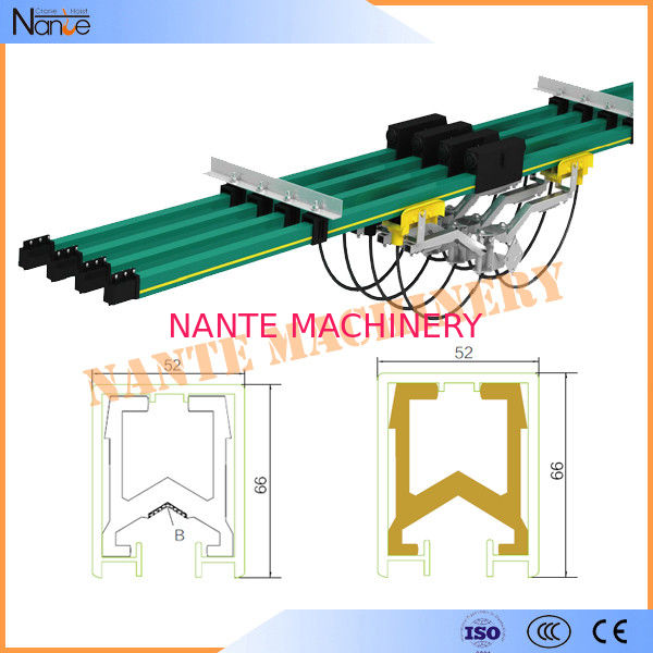
The JDC-H conductor rail system is a modern power supply system using single pole insulated conductor rails. It complies with the latest regulations and provides the electric energy for material handling equipments such as overhead cranes.
The aluminum conductor rail is provided with a proven and patented stainless steel contact surface. Any numbers of poles can be installed vertically or horizontally, on straight or curved systems.
The entire conductor rail system can be installed indoor or outdoor. It is insulated conforming to Current Safety Regulations. Ground insulation cover is marked yellow-green on one side over the entire length of the rail.
R Type: for curves R≥1200mm.
Approved and listed by: CCC, ISO9001 and CE.
Application
The ranges of applications of JDC Insulated Conductor System:
- Overhead and elongated tracks for cranes.
- Electric hoists, electric tools, stacking systems, monorail systems.
- Monorail systems.
- Other applications for supplying power to moving power load.
Design features
- Compact and flexible arrangement for poles.
- High safety insulation housing, corrosion resistance.
- Easy and exact mounting with multiple supporting bracket.
- Easy installation.
- Variation in temperature, large power available.
Housing:
Generally, the housing line is in green and ground line in yellow-green. Standard length is 4m or 6m, other sections are available.
Joints:
Snap-in joint splices provide mechanical and electrical continuity. Insulated protection covers are included.
Feed Sets:
End feeds or line feeds are available.
End Caps:
The open ends of the conductor are closed by end caps.
Hangers:
Standard brackets for conductor attachment to crane girders are available. Conductor is with sliding and fix point hangers.
Standard distance between suspension appoints for indoor and outdoor installations: 1500mm to 2000mm.
Expansion Section:
The Expansion sections are required to compensate the different expansions between copper conductors and steel-or concrete structures, in varying temperatures without interrupting electrical power.
Expansion joints are used when the Powerail length between feeds, curves, switches or other fix points is exceeding 20m. Install expansion joint according to actually installation.
Isolating Section:
Isolating sections are required if parts of the system or individual rails are to be de-energized within a conductor rail system. To prevent a voltage bridging by current collector two air gap isolating sections should be installed.
Collectors:
The current collectors are made of carbon brush, reinforced nylon and galvanized or spray-paint metal material. Spring loaded carbon brushes maintain uniform contact. Connecting cables and hinged or flexible towing arms included. Double Current collectors for transfer applications and higher amperage are available.

Technical Parameters
| Model |
Type |
Conductor material |
Cross section(mm²) |
Nominal current (A) |
Leakage-distance (mm) |
Resistance |
Dimensions (H * W) |
Weight(kg) |
| JDC-H-100/150 |
H19 |
Aluminum |
100 |
150 |
35 or 80 |
0.376 |
25*19 |
0.46 |
| JDC-H-160/250 |
H24 |
Aluminum |
160 |
250 |
45 or 80 |
0.203 |
32*24 |
0.63 |
| JDC-H-180/300 |
H24 |
Aluminum |
180 |
300 |
45 or 80 |
0.187 |
32*24 |
0.71 |
| JDC-H-230/320 |
H32 |
Aluminum |
230 |
320 |
80 |
0.153 |
42*32 |
0.96 |
| JDC-H-285/500 |
H32 |
Aluminum |
285 |
500 |
80 |
0.116 |
42*32 |
1.13 |
| JDC-H-360/630 |
H32 |
Aluminum |
360 |
630 |
80 |
0.087 |
42*32 |
1.38 |
| JDC-H-420/800 |
H32 |
Aluminum |
450 |
800 |
80 |
0.067 |
42*32 |
1.5 |
| JDC-H-550/1000 |
H32 |
Aluminum |
550 |
1000 |
80 |
0.058 |
42*32 |
1.83 |
| JDC-H-600/1250 |
H32 |
Aluminum |
600 |
1250 |
80 |
0.046 |
42*32 |
2.01 |
| JDC-H-700/1250 |
H52 |
Aluminum |
700 |
1250 |
100 |
0.043 |
66*52 |
2.58 |
| JDC-H-1100/1600 |
H52 |
Aluminum |
1100 |
1600 |
100 |
0.037 |
66*52 |
3.65 |
| JDC-H-1350/2500 |
H52 |
Aluminum |
1350 |
2000 |
100 |
0.028 |
66*52 |
4.32 |
| JDC-H-1600/2500 |
H52 |
Aluminum |
1600 |
2500 |
100 |
0.018 |
66*52 |
4.99 |
| JDC-H-2000/3000 |
H52 |
Aluminum |
2000 |
3000 |
100 |
0.015 |
66*52 |
6.07 |
| JDC-H Conductor Rail System |
| Conductor Rail Material |
Aluminum |
Copper |
Stainless steel |
| Type |
H19 |
H24 |
H32 |
H35 |
H52 |
H19 |
H24 |
H32 |
H52 |
H19 |
| Nominal current at |
150 |
250-300 |
320-1250 |
230
-800
|
1250
-3000
|
150-500 |
500-800 |
800-1600 |
1250-5000 |
25 |
| 100%DC and 35°C(A) |
| DC resistance(Ω/km) |
0.376 |
0.203-0.187 |
0.153-0.046 |
0.153- 0.067 |
0.043- 0.015 |
0.376- 0.156 |
0.116-0.067 |
0.067-0.039 |
0.036-0.007 |
11.652 |
| Impedance(Ω/km) |
0.381 |
0.209-0.195 |
0.155-0.048 |
0.155- 0.069 |
0.044
-0.017
|
0.377- 0.158 |
0.118-0.069 |
0.069-0.040 |
0.038-0.008 |
11.663 |
| Distance between each suspension bracket (m) |
1.5 |
1.5 |
1.8 |
1.8 |
2 |
1.5 |
1.5 |
1.8 |
2 |
1.5 |
| Rail Length/PC (m) |
4.5 |
6 |
6 |
6 |
6 |
4.5 |
6 |
6 |
6 |
4.5 |
| Housing Length/PC (m) |
4.42 |
5.88 |
5.83 |
5.83 |
5.75 |
4.42 |
5.88 |
5.83 |
5.75 |
4.42 |
| Max. voltage (v) |
660v |
Dielectric strength (kv/mm) |
30-40 |
| Travelling speed |
≤600m/min |
Design and Manufacturing Standard |
GB7251.2-2006 |
| Expansion joint |
Cannot exceed 200m length |
| Flame retardant |
Class B1-no flaming particles, self-extinguishing |
| Permissible Ambient temperature |
Standard insulation -30°C- +70°C|High temperature insulation -20°C- +115°C|Low temperature insulation -40°C- +85°C |